


Here's the problem; you've always wanted to know more about how computers work at a fundamental level. You've got some basic knowledge of electronics from a theoretical level; but haven't really done much in the way of practical electronics.
I found the solution!

Ben Eater is an extraordinarily talented communicator and teacher and has managed to build a simple computer on a bunch of breadboards as a way to teach how the various parts of a modern computer work. His videos are incredibly detailed and go through everything in small steps. You follow each video; copying Ben as he explains how and why everything is the way it is. Slowly, a computer takes shape at your desk, with a clock, bus, RAM, CPU, program counter, display, etc etc.
I followed the videos and completed the computer in about two months of spare time. It is extremely satisfying to build it all up piece by piece and see all the parts working. It can be programmed just like a normal computer (limited to the ADD and SUB functions) to do simple 8-bit arithmetic (i.e. up to values of 255). Not only that; but I really understand computing in a way I didn't before.
The first video in the series can be found here.
Cost
The one downside of this project is that it costs a fair sum (components alone are around £350 in total, spread across a few months). I bought my components mostly from Mouser; with the odd few coming from Ebay if they are more rare (the RAM chips are a good example). Consider bulk buying a "kit" for resistors, capacitors (electrolytic and ceramic) and simple logic gate chips as you use them frequently.
There is a LOT of therapeutic wire cutting and stripping so buy a good 50m of different coloured 22 gauge copper wire, see for example here, along with some wire strippers and a decent pair of pliers (trust me on the quality of the pliers). Black for ground, red for power. At least three other colours.
Another big cost comes from the breadboards onto which the various parts of the computer are placed. You need a lot (16 minimum); and although the more expensive ones will have fewer power distribution problems, it will become very costly with those. I used much cheaper ones (around £3 each); but be prepared to add more power rails everywhere when you assemble the final configuration.
Power Supply
The easiest way to power the computer is using a 5V mobile phone charger. If you have a spare lying around check the plastic casing of the transformer, it should be rated 5V DC. Cut the end of the cable and strip the red/black wires (these can be stuck straight in the breadboard). Check with a multimeter that the voltage is correct; and this supply should be more than adequate for the computer. These are very low power so don't worry about getting any sort of nasty shock.
The difficult part of the power supply is providing enough current; the full computer draws rather a lot of it due to the inefficient power distribution across all the wires and components. My final computer takes around 0.6A. This is no problem from the mains supply; but if you try to run it from batteries be prepared to use quite a few of them (I needed 4 9V cells).
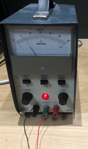
Alternatively; you can buy a DC power supply (Ebay has got some good low price supplies) and link it up directly to the breadboards (see pictures below of my one).


Mounting it on the wall
I was pretty happy with the final computer; when its performing calculations its very satisfying to watch all the diagnostic LEDs flicker on and off as the data is moved around from memory to CPU to display.
I decided it would be good to put it up on the wall.
To do this; I bought a deep box frame from Amazon. The breadboards all have an adhesive backing, so I carefully stuck the computer to the backing of the frame (try placing a pillow over the circuitry, carefully upturning the pillow and then sticking the backing to the breadboards).
Having trailing wires to the nearest plug sockets will look ugly; so this thing needs battery power! I drilled a little hole in the side and put a simple rocker switch there. The switch is attached to a 5V power supply module from ebay (be very careful of the voltage regulator as it gets HOT, I burnt my arm on it almost immediately). If you have a spare heat sink; its worth using it on the regulator.


The power supply can be screwed into the inside of the box frame. Four 9V cells are attached to the power supply in parallel in order to provide enough current.
Now the box frame can be hung on the wall and will execute your programmed code at the flick of a switch. It's a very impressive looking wall hanging; and even better once you know exactly how it works.

Comments